AFC 300 Manual
AFC 300 Alternator Regulator
1Introduction
Thank you for purchasing our product. You are already ahead of the game by consulting the manual.
This document contains instructions for installing and operating the MG AFC 300 Alternator Regulator. Please read this manual carefully before use and keep this document for future reference.
1.1Legal notice and disclaimer
© 2026 MG Energy Systems B.V. All rights reserved.
This manual is the property of MG Energy Systems B.V. and is solely intended for the use of MG Energy Systems B.V. products.
No part of this publication may be reproduced, translated, or distributed in any form or by any means without the prior written permission.
MG Energy Systems B.V. makes every reasonable effort to ensure that the information in this manual is accurate and complete. The instructions in the manual are based on the relevant laws and regulations applicable at the time of publication or when the product was placed on the market. MG Energy Systems B.V. reserves the right to modify the manual at any time without notice. Please consult the website for the latest version of the manual. MG Energy Systems B.V. accepts no liability for any errors or omissions in the manual and is not liable for damages resulting from the use of the manual.
The product shall only be used in accordance with the instructions provided in this manual. Any other use, including improper installation, operation, or modification, may lead to unsafe conditions and void any warranty. MG Energy Systems B.V. shall not be liable for material damage or personal injury resulting from improper, careless, or unintended use of the product.
2Safety instructions
To avoid possible harm, read and follow these safety instructions.
2.1Warning symbols
This manual contains following symbols to indicate potential hazards. Read the warning messages carefully to ensure that you are familiar with the safety signs.
Table 1:Warning symbols and description
| Symbol | Title | Description |
|---|---|---|
 | Tip | This signal word indicates useful information or recommendations. Disregarding this tip will not result in injury or damage. |
 | Attention | This signal word provides important operational or procedural instructions and requires careful consideration to ensure correct usage of the product. Disregarding this instruction could result in product or property damage, but will not lead to personal injury. |
 | Warning / Electrical Hazard | The Warning signal word indicates a high level of risk which, if the hazard is not avoided, could result in serious injury or death. The Electrical Hazard signal word signifies a danger of high electrical voltage, which can cause electric shock. Take necessary precautions to avoid possible harm. |
 | Danger | This signal word indicates an immediate and extreme hazardous situation. Failure to avoid this situation could result in death or very serious injury. |
2.2User safety
Ensuring the health and safety of all users is a top priority. Read and follow these safety precautions to prevent any injury.
Read all instructions before use.
Wear appropriate personal protective equipment (PPE) when working on a battery system.
Never touch electrical components with wet hands or while standing on wet surfaces.
Use insulated tools when working on a battery system.
Ensure that local regulations for working on battery systems are followed.
2.3Product safety
This product is designed and tested in accordance with international standards. The equipment may only be used for its intended purpose.
Treat the product as described in this manual.
Ensure that the equipment is used under the correct operating conditions. The operating limits on the identification label must not be exceeded under any circumstances.
Never operate the product in a wet or dusty environment.
Don’t crush, heat, incinerate, short-circuit, dismantle or immerse in any liquid.
Do not install, modify, or repair the AFC 300 while the system is in operation or energized, as this may result in damage to the alternator and/or field regulator.
2.4Terms and definitions
For a list of terms, abbreviations and their descriptions, please consult the glossary in the Appendix. (Section 8.1)
3Product description
The MG AFC 300 is an alternator field regulator, designed to charge an MG battery system under optimal conditions. By regulating the alternator’s field current, the AFC 300 controls excitation to maintain stable and efficient charging. It also measures the temperature to protect the alternator against overheating and the built-in load dump protection shields all connected equipment from damage caused by transient voltage surges.
The AFC 300 supports a wide variety of alternators that are compatible with external field control. The AFC 300 is suitable for 12 V, 24 V and 48 V alternators and is only compatible with MG battery systems.
This product is designed and tested in accordance with international standards. The equipment should be used according to the intended use only.
3.1Intended use
The AFC 300 serves as alternator regulator to charge an MG battery system. The AFC must be connected to the field wire(s) of the alternator on one end and to the Master Battery Management System (Master BMS) on the other end, enabling control of the alternator excitation. Supported Master BMS units are the MG Master LV and the MG SmartConnect. The AFC 300 is controlled by the Master BMS and operates according to its parameters via the NMEA2000 CAN bus. Alternatively, the AFC 300 can be connected to the MG SmartLink MX, which is also capable of controlling the device.
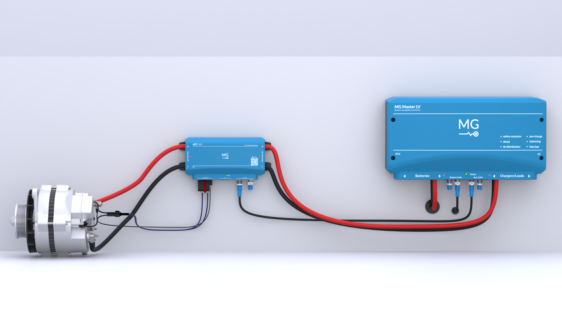
Figure 1:AFC installation example with alternator and MG Master LV
The AFC 300 is capable to automatically detect what kind of field is connected. It is mandatory to add the temperature sensor to the alternator and connect it to the AFC 300. Multiple AFC 300 devices can be connected in parallel. Settings can be adjusted via the MG Connect App, which connects to the integrated Bluetooth module.
This product is not designed for use or play by young children.
Never operate the product in a wet or dusty environment.
Wiring diagrams of system examples with the MG AFC 300 are available on the MG website and the MG Download Center, see Single-line diagrams.
3.2Product specifications
Visual of the product’s enclosure design:
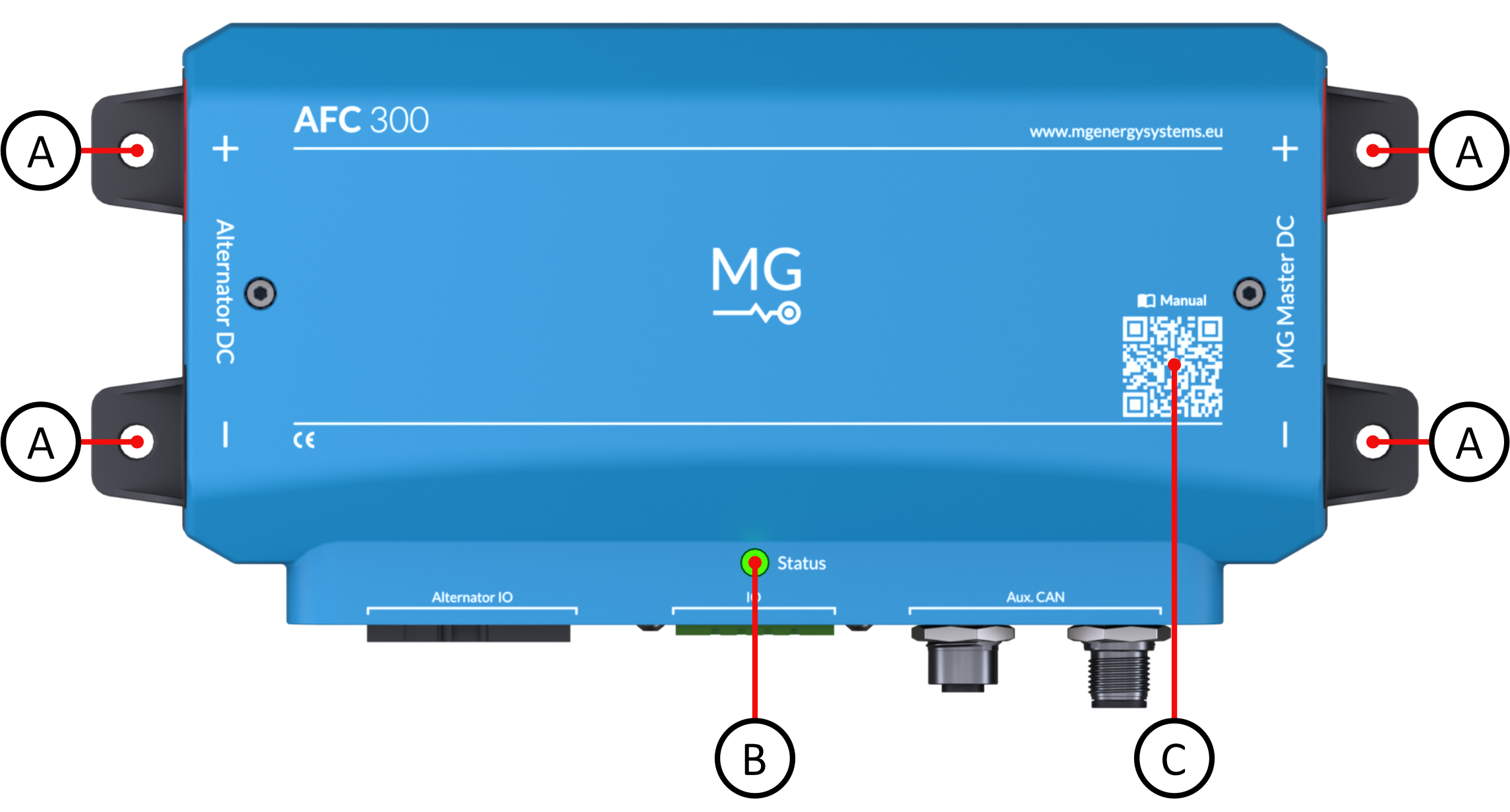
Figure 2:Top view AFC
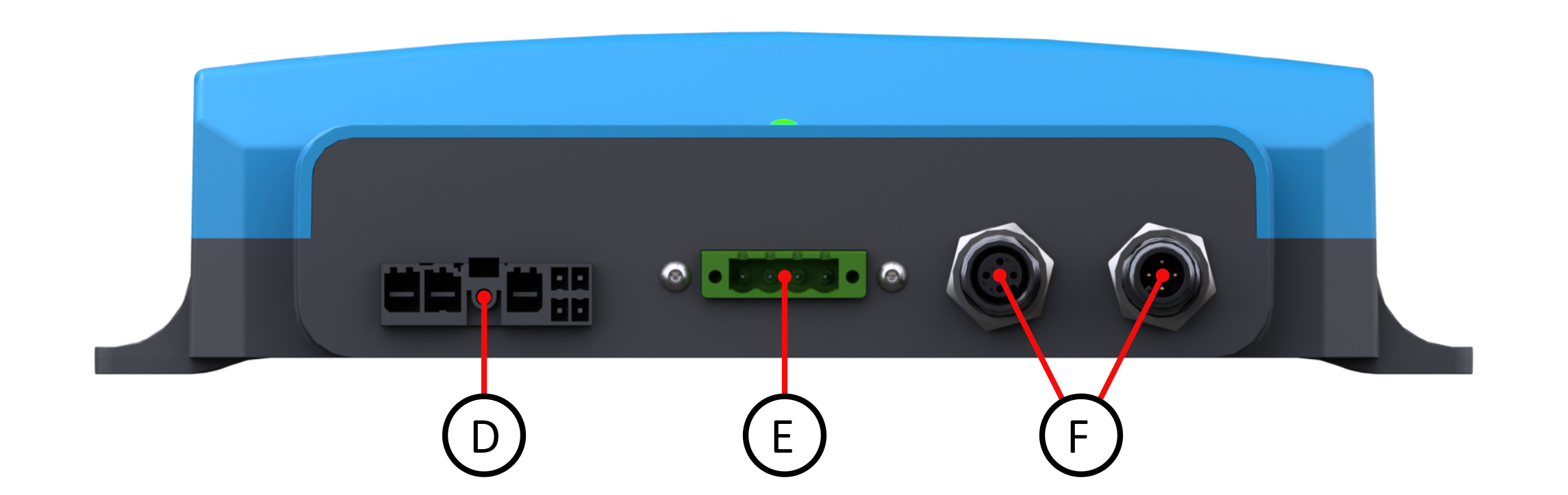
Figure 3:Front view AFC
| Part | Description |
|---|---|
| A | Mounting points |
| B | Status LED |
| C | QR-code for manual |
| D | Alternator connector |
| E | IO connector |
| F | M12 isolated CAN bus |
Visual of the product’s internal design:
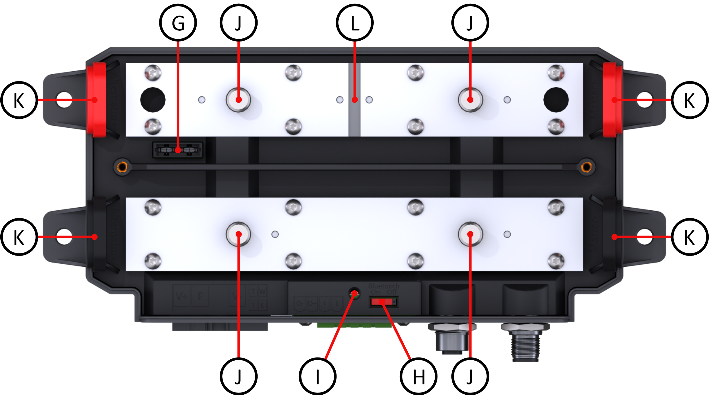
Figure 4:Internal design AFC
| Part | Description |
|---|---|
| G | Fuse holder |
| H | Bluetooth switch |
| I | Status LED |
| J | Power connection bolt |
| K | Cable grommet |
| L | Shunt |
3.2.1Technical specifications
The technical specifications are provided in the Appendix (Section 8.2). Please ensure that you follow the specifications. The latest version is always available on the MG Download Center, see AFC 300 Data Sheet.
4Installation phase
Please read first the safety instructions, to make yourself familiar with the safety symbols and guidelines before installing and using this product.
4.1Scope of delivery
Please refer to Table 2 to see which products are included in the box.
Table 2:Scope of delivery
| Article | Article number |
|---|---|
| MG AFC 300 | MGAFC480300 |
| IO connector | MG5001095 |
| Alternator connector | MG5001094 |
| Temperature sensor | MG3000438 |
| Fuse FKS ATO 20A | MG5001100 |
| Quick installation guide | MG4000680 |
4.2Unpacking
Follow these guidelines when handling the product to prevent damage during unpacking:
Handle the product with care.
Inspect the product for damage before use.
Leave the protective caps and covers on the product until installation.
Inspect if the identification label is visible and readable.
Keep the packaging in case transportation is needed in the future.
Identification label
Important information is found on the identification label, such as supply voltage range, maximum current and the serial number of the product.
There are two identification labels located on the AFC 300; one at the bottom side of the device, and one on the inside when the cover is removed.
See Figure 5 and Figure 6 for an example.
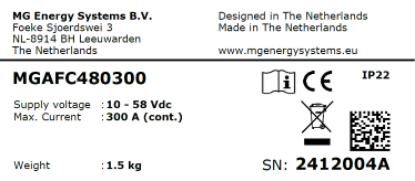
Figure 5:Example identification label (external, at the bottom side of the device)
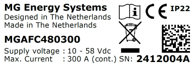
Figure 6:Example identification label (internal, at the back side of the device)
See Table 3 for the explanation of the symbols used on the label.
Table 3:Explanation identification label
| Symbol | Meaning |
|---|---|
 | Declaration of conformity with health, safety, and environmental protection standards for products sold within the European Economic Area as per directive 2014/35/EU. |
 | Symbol indication the manual must be read before installation and use of the device. |
 | Device is treated according the Waste Electrical and Electronic Equipment (WEEE) Directive 2012/19/EU. |
 | GS1 data matrix type barcode containing detailed product information. |
Bluetooth label
A Bluetooth label with PUK code can be found when the cover is removed, at the back side of the device.
In case the PIN code is forgotten, use this PUK code to get access to the Bluetooth module.
The internal Bluetooth module in the AFC 300 is enabled by default. It can be turned on/off by using the internal red switch. See the product specifications (Section 3.2) for its location. Chapter Configuration (Section 4.6.1) explains how to connect to the Bluetooth.
4.3Preparing
The information in this chapter and the following media will help you prepare for the installation of the product.
Watch the MG AFC 300 installation video.
Consult the AFC Quick Installation Guide.
Location and environment
The AFC 300 has an IP22 rating.
It must be placed in a space that is free of moisture and dust, non-condensing, and protected against ingress of liquids (water, oil, etc) from above and below.
For example, it is not allowed to install it under the seams of hatches.
Install the product in an environment that can tolerate some heat. Ensure that there are no chemicals, plastic parts, curtains or other textiles in the immediate vicinity of the equipment. Ensure that there is always sufficient free space around the product.
Environmental conditions:
Ambient temperature: -20 to +50 °C
Humidity (non-condensing): ≤ 95 %
Tooling
Use proper tools when installing. The required tools are:
Fastening tool of choice for the mounting procedure
Insulated screwdriver PH2
Cutter knife
Insulated torque wrench 30 Nm with 17 mm socket (M10)
Battery system
Before continuing with the installation procedure, make sure that the battery system is turned off and there is no voltage left on the system.
4.4Mounting
Mount the AFC 300 vertically or horizontally on a flat surface using the 4 mounting holes on the side of the device. Ensure there is sufficient space for all connections. The maximum fastener size that fits in the mounting holes is M6 (1/4").
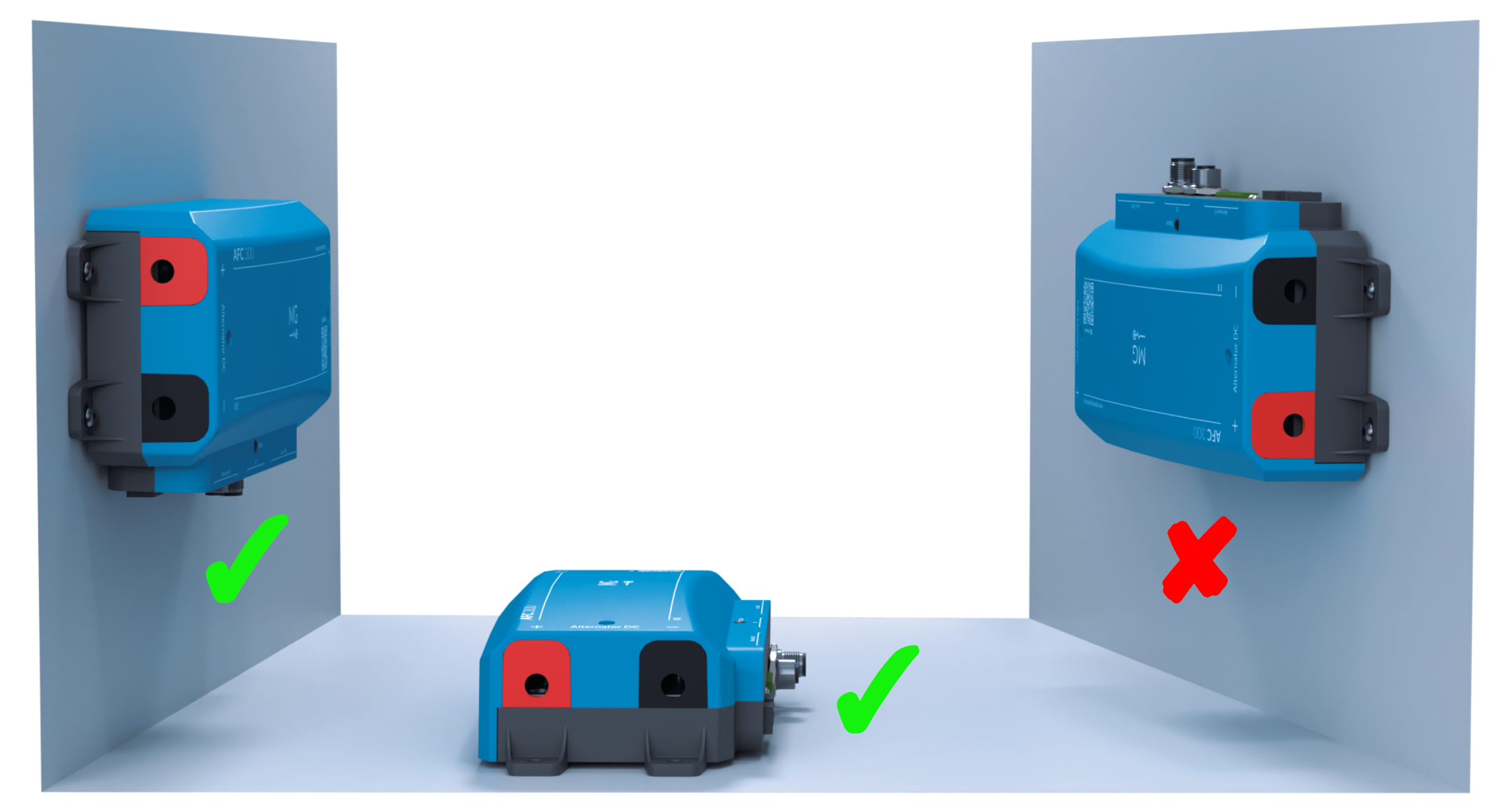
Figure 7:Mounting direction
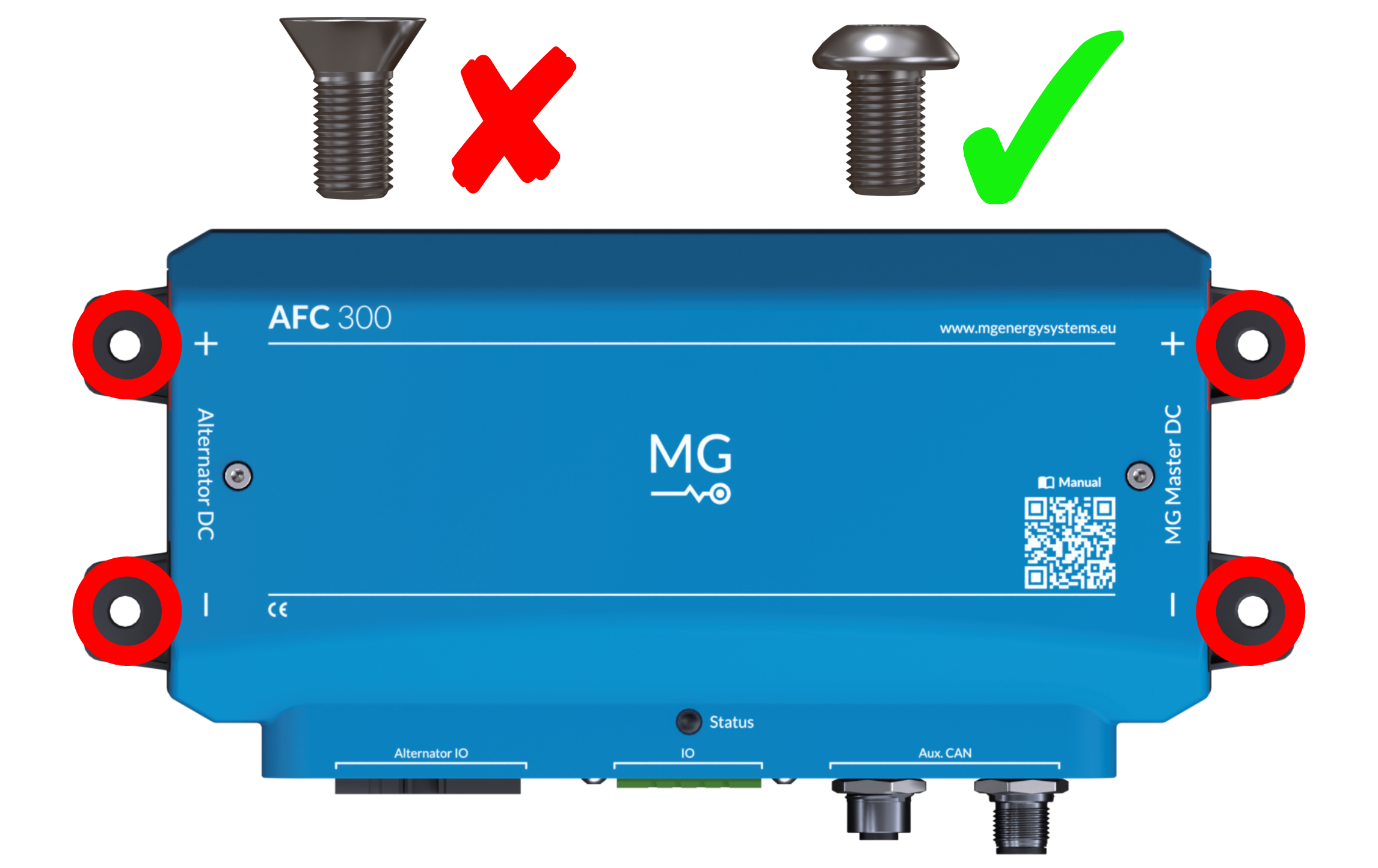
Figure 8:Mounting screws
4.5Connecting
4.5.1Connect power cables
After this step, the product should look like this:
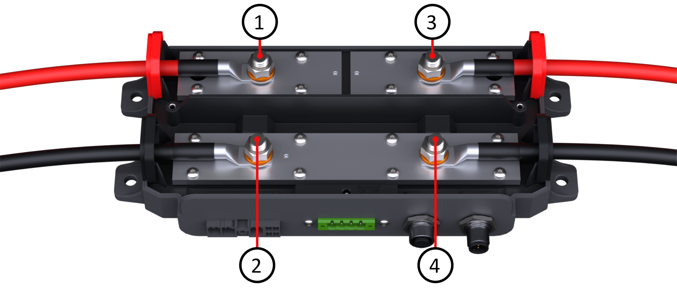
Figure 9:AFC 300 Power connections
See Table 4 for the power connection specifications.
Table 4:Power connection specifications
| Name/Purpose | Bolt | Voltage | Current | Cable | Size |
|---|---|---|---|---|---|
| Alternator + | 1 | ≤ 58 VDC | ≤ 300 A | 120 mm² (250 MCM) | M10 |
| Alternator - | 2 | GND | ≤ 300 A | 120 mm² (250 MCM) | M10 |
| Master BMS + | 3 | ≤ 58 VDC | ≤ 300 A | 120 mm² (250 MCM) | M10 |
| Master BMS - | 4 | GNC | ≤ 300 A | 120 mm² (250 MCM) | M10 |
Installation steps power cables
Step 1/7
Remove the top cover of the device with screwdriver PH2.
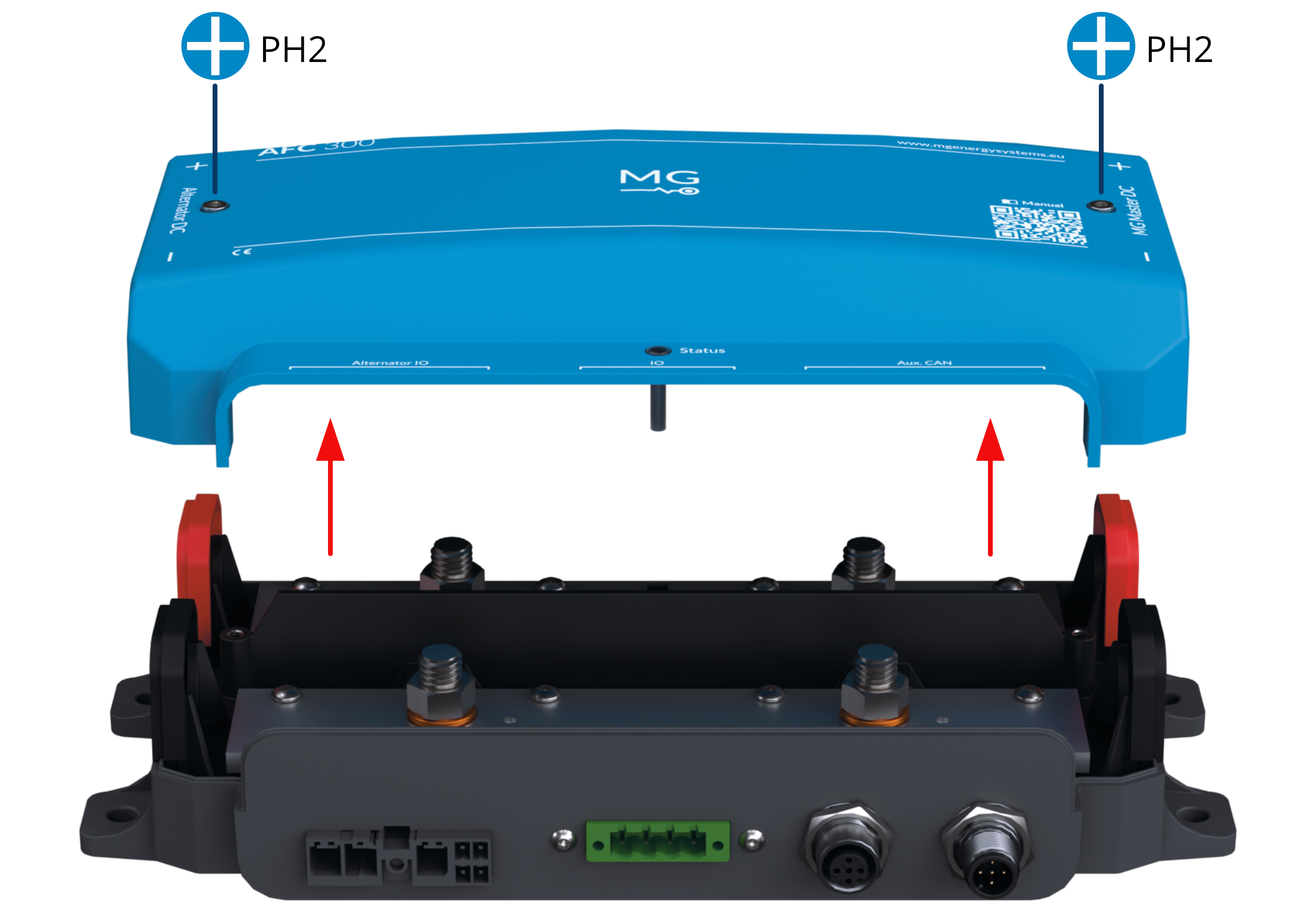
Figure 10:Remove top cover
Step 2/7
Remove the cable grommets and cut them to the appropriate cable size.
Place the grommet on each power cable, attach a cable lug with crimping tube to each cable end and seal with a heat shrink tube.
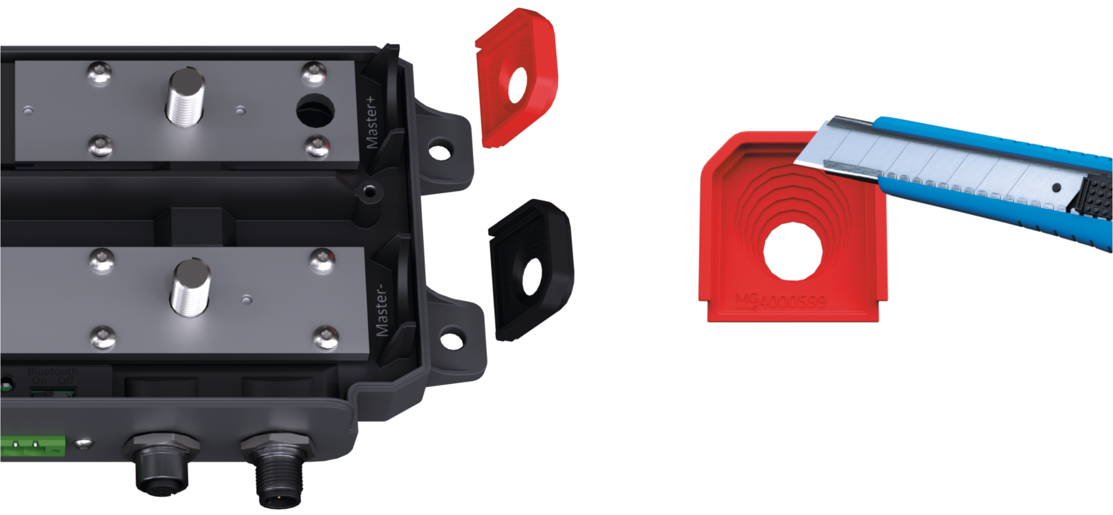
Figure 11:Cut cable grommet
Step 3/7
Remove the nut (1), spring washer (2) and washer (3) from all four power connection bolts.
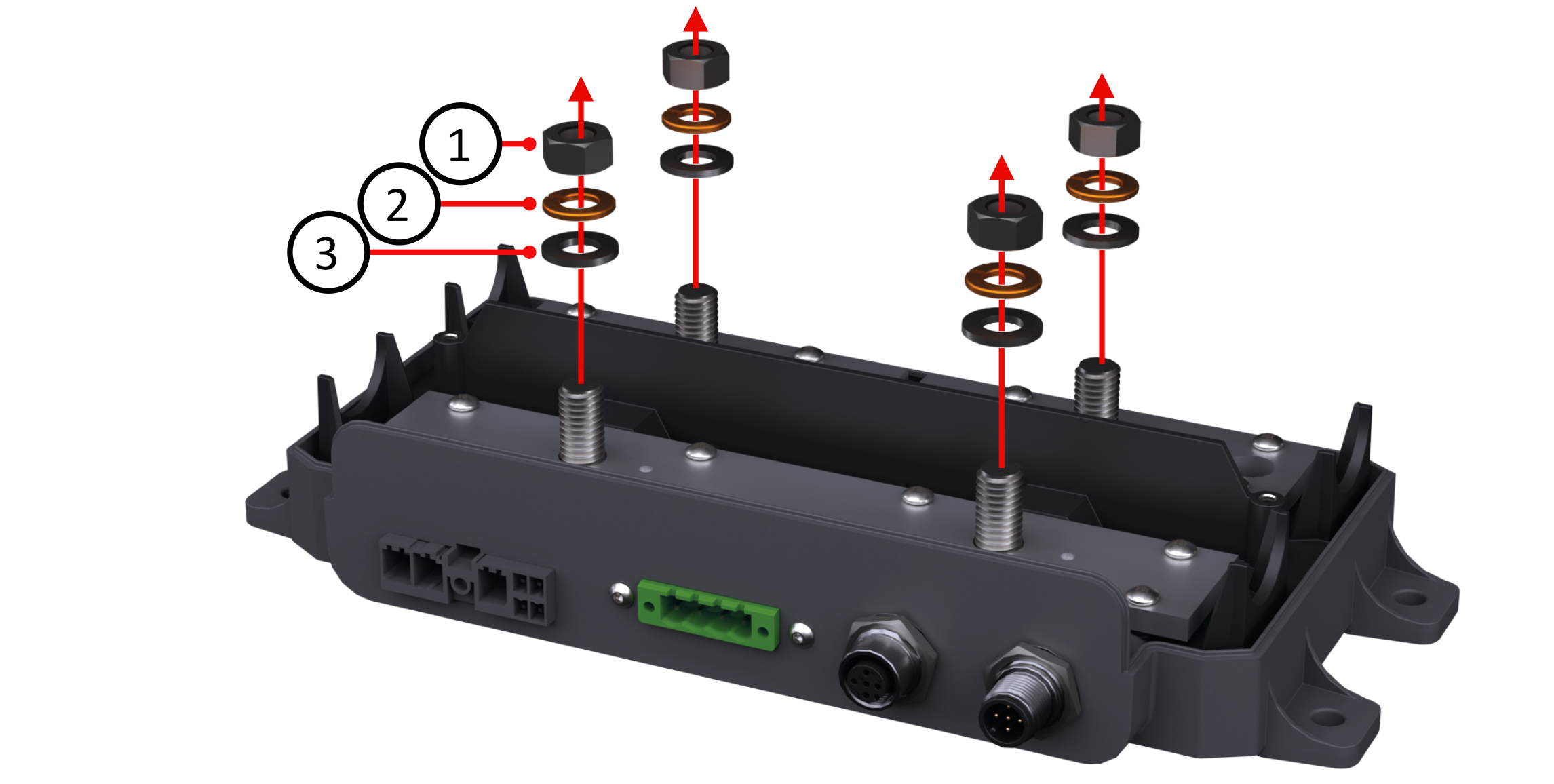
Figure 12:Remove nut, spring washer and washers from all bolts
Step 4/7
Place the alternator power cables (4) with grommet on the bolts and place the washer (3), spring washer (2) and nut (1) on the bolt.
Tighten the M10 nut with 30 Nm (22 lb-ft).
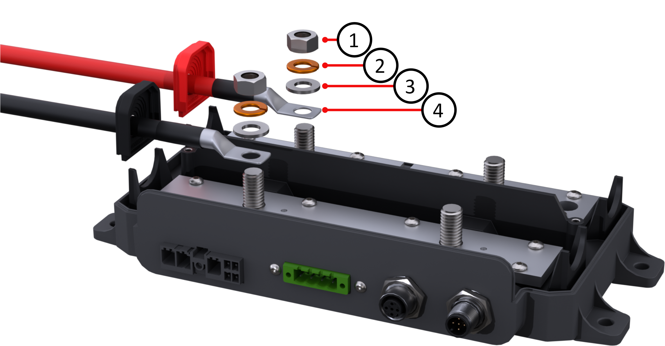
Figure 13:Place power cable alternator side
Step 5/7
Place the power cables going to the Master LV (or to the SmartConnect battery) (4) on the bolts and place the washer (3), spring washer (2) and nut (1) back on the bolt.
Tighten the nut with 30 Nm (22 lb-ft). It is recommended to fuse these cables appropriately; this can be done, for example, inside the MG Master LV.
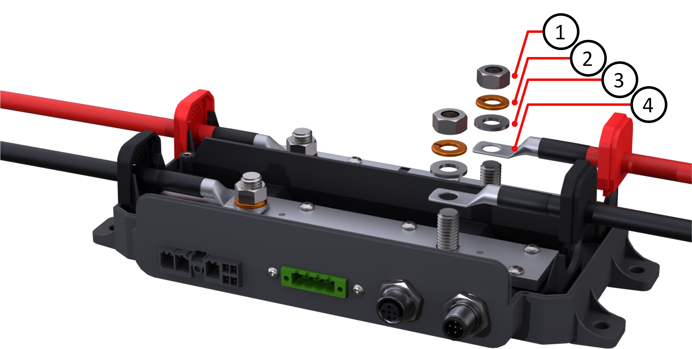
Figure 14:Place power cable Master LV side
Step 6/7
(optional) Place the appropriate fuse in the assigned place in the AFC 300. See Table 13 for the applicable fuse types.
There is no internal fuse needed when the field is supplied by an external power supply.
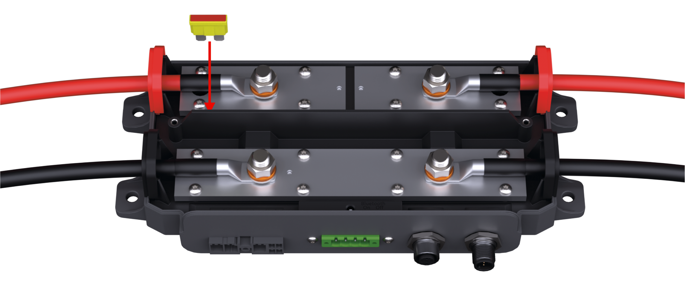
Figure 15:Place fuse (optional)
Step 7/7
Mount the top cover on the device.
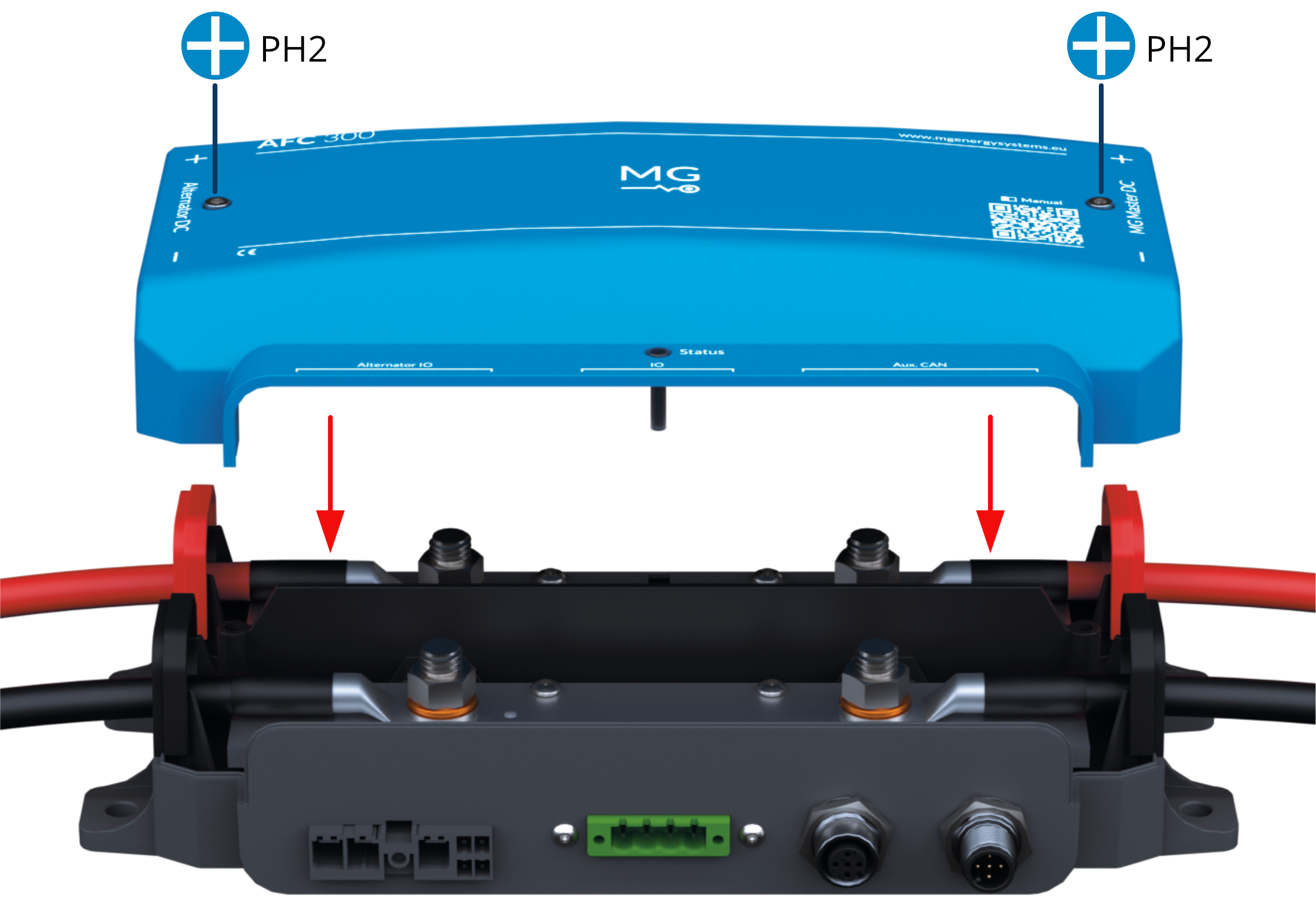
Figure 16:Mount top cover
4.5.2Connect CAN bus
The connectors used for connecting the CAN bus are circular M12 with 5 positions and A-coded keying.
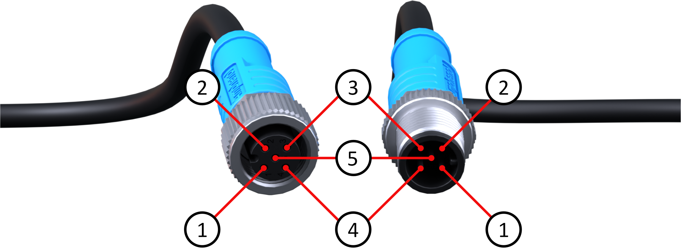
Figure 17:M12 CAN bus connector pinout
Table 5:M12 connector pin specifications
| Pin | Name/Purpose | Voltage | Current |
|---|---|---|---|
| 1 | Shield | ||
| 2 | VCC | ≤ 58 VDC | ≤ 1 A |
| 3 | GND | ≤ 1 A | |
| 4 | CAN-H | ||
| 5 | CAN-L |
Compatible cables are NMEA 2000 and DeviceNet.
Minimum requirements for the cables:
Cable with braided shielding connected to pin 1.
Pair of conductors connected to pin 2 and 3 for power and HVIL with a minimum wire cross-sectional area of 0.34 mm² (22 AWG).
Twisted pair connected to pins 4 and 5 for communication with a minimum wire cross-sectional area of 0.2 mm² (24 AWG).
Installation steps CAN bus
Step 1/2
Connect the Aux. CAN bus of the AFC 300 to the Aux. CAN bus of the MG Master LV, MG SmartConnect or MG SmartLink MX.
Hand-tight is sufficient, don’t use any tool to tighten the connector.
Step 2/2
If it is the last device on the bus, make sure to use a terminator to close the bus.
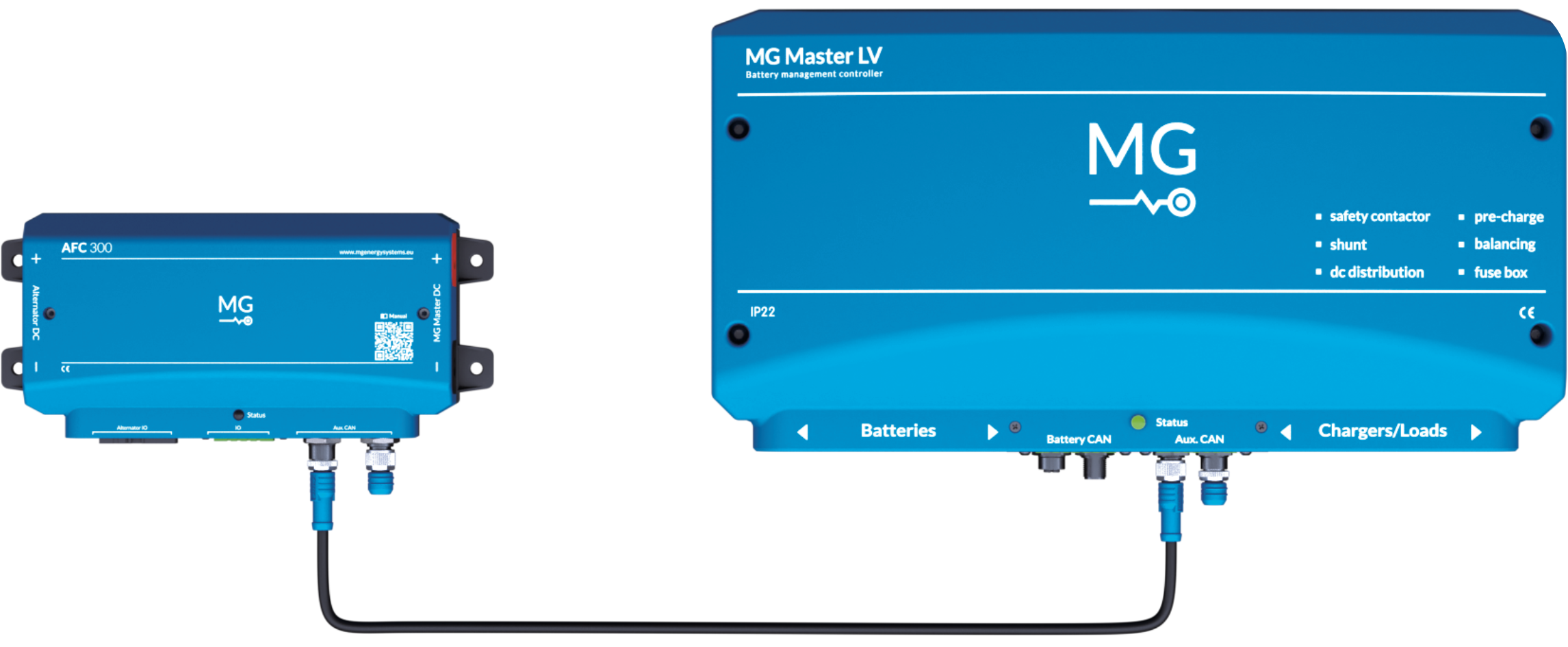
Figure 18:Connect CAN bus
4.5.3Connect alternator connector
Figure 19 shows the alternator connector on the AFC 300. Table 6 and Table 7 provide its specifications.
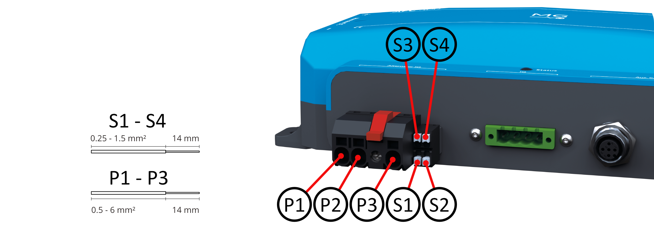
Figure 19:Alternator connector
Table 6:Alternator connector Power connections
| P1 - P3 | Power connections | IO | Voltage | Current |
|---|---|---|---|---|
| P1 | Field power supply + | In/Out | ≤ 58 VDC | ≤ 20 A |
| P2 | Field | Out | GND | ≤ 20 A |
| P3 | Field power supply - | In/Out | GND | ≤ 20 A |
Table 7:Alternator connector Signal connections
| S1 - S4 | Signal connections | IO | Voltage | Current |
|---|---|---|---|---|
| S1 | Alternator Temperature 1 | In | GND | |
| S2 | Ignition/Enable (7-58 VDC input for active detect) | In | ≤ 58 VDC | < 1 mA |
| S3 | Alternator Temperature 2 | In | ≤ 58 VDC | < 1 mA |
| S4 | W/Tacho (Stator signal) | In | ≤ 58 VDC |
Installation steps alternator connector
Step 1/4
To install a power connection wire (P1, P2 or P3) to the connector:
Strip 14 mm of insulation from the end of the wire. Optionally, attach a wire end ferrule.
Press the white actuator (lever/pusher) in the direction of arrow 1 in Figure 20 to open the internal connector clamp. A screwdriver may be used if necessary.
Insert the wire fully into the connector opening, in the direction of arrow 2 in Figure 20.
Release the actuator to clamp the wire securely inside the connector. Optionally use a screwdriver to press the actuator slightly downwards so that it releases. (See direction of arrow 3 in Figure 20)
Gently pull the wire to confirm it is firmly locked.
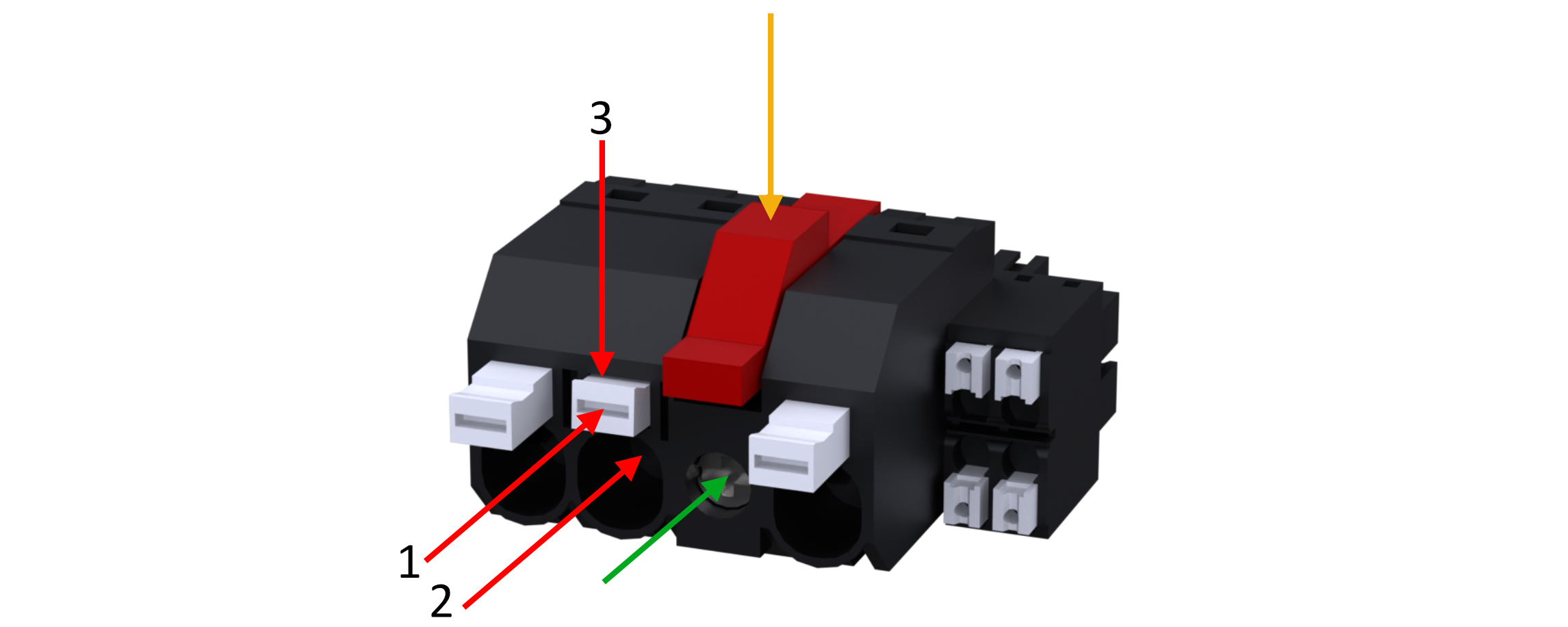
Figure 20:Install power wire to alternator connector
Step 2/4
To install a signal connection wire (S1-S4) to the connector:
If the signal wire contains a wire end ferrule or solid core, insert the signal wire directly.
For stranded wire without a wire end ferrule, press the actuator when inserting the wire. Release the actuator when the wire is fully inserted.
Step 3/4
Connect the alternator connector to the AFC 300.
Step 4/4
(optional) To fasten the connector more secure, tighten the screw in the front of the connector. (See green arrow in Figure 20)
To disconnect the connector from the AFC 300, the red latch must be pressed down. (See yellow arrow in Figure 20)
Field wires: P2 & P3
Option 1: Alternator with N- or P-type field.
One end of the winding is available on the outside of the alternator. Connect this field wire (1) to the P2 connection.
The AFC 300 will detect automatically which type is connected and drive the field accordingly.
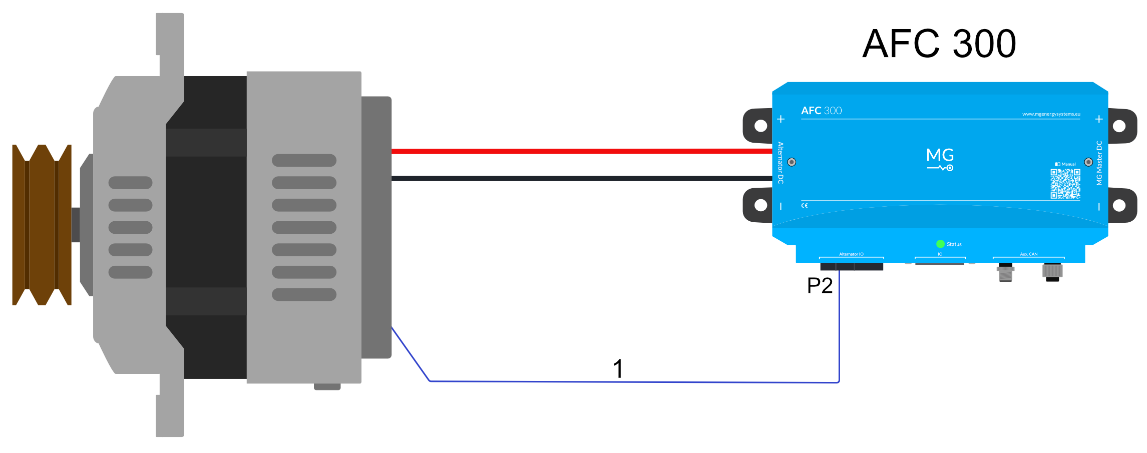
Figure 21:Alternator N/P-Type field wire (1)
Option 2: Alternator with 2 field wires.
Both ends of the field windings are available on the outside of the alternator.
Connect one of the field wires to P3 or to the negative terminal on the alternator.
Connect the other field wire to the P2 connection. With this connection the field is wired as P-type, which is recommended.
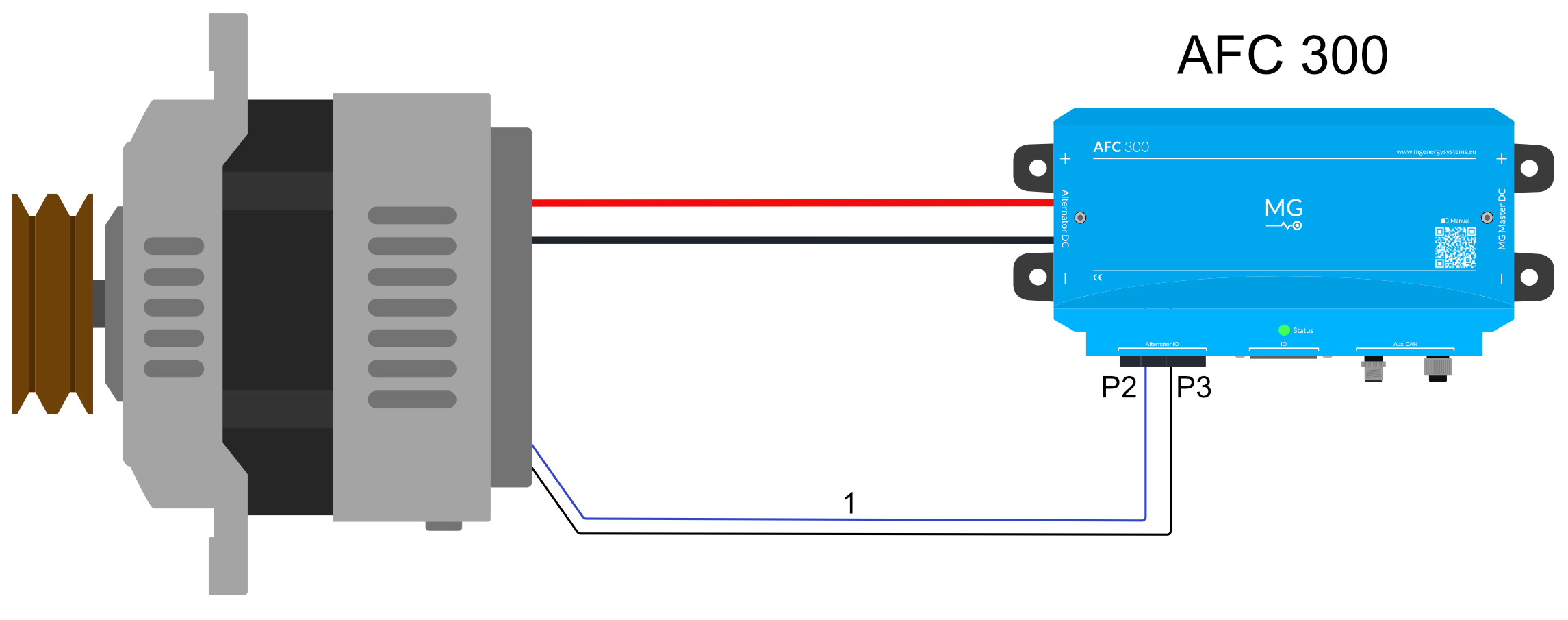
Figure 22:Alternator with 2 field wires (1)
Field with external PSU: P1 (optional)
The field excitation voltage may optionally be supplied by an external power source. See Figure 23 and Figure 24 for a single-line diagram.
To install the external power supply correctly, follow next steps:
Make sure there is no fuse installed in the AFC 300.
Connect the external power supply negative wire to P3.
Connect the external power supply positive wire to P1.
Connect the field wire of the alternator to P2.
Configure the settings accordingly, so no broken fuse warning will be generated. See Settings (Use external field power).
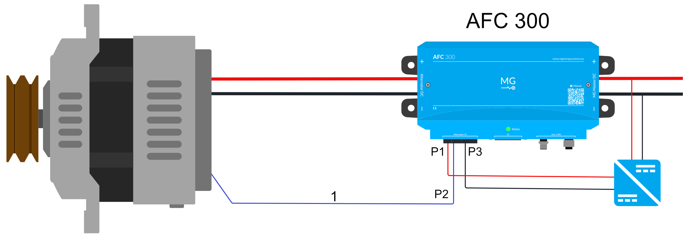
Figure 23:Alternator field wire (1) with external power supply
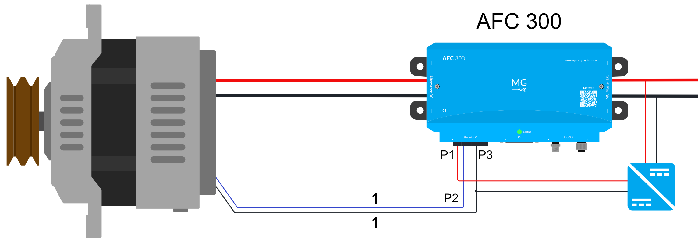
Figure 24:Alternator 2 field wires (1) with external power supply
Temperature sensor: S1 & S3
It is mandatory to connect the temperature sensor. Only use the temperature sensor supplied with the device.
Connect the temperature sensor cable lug to the alternator. (see tip)
Add a wire end ferrule to both ends of the temperature sensor.
Insert the temperature sensor wires to S1 and S3 of the AFC 300 alternator connector. (see Figure 19)
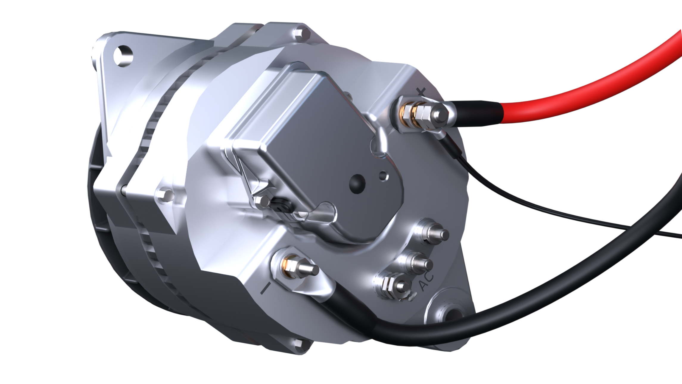
Figure 25:Temperature sensor connected to positive terminal
Ignition/enable wire: S2 (optional)
This connection can be used when an external control of the AFC 300 is required to start or stop the charging process. For example, an external oil pressure sensor or a signal from the engine control unit, to allow charging only when the engine is running.
In case this option is used:
This function is on by default.
The AFC 300 will start as normal, when the input is high.
When the signal is low, the AFC 300 will not enter standby mode and will not drive the field.
In case this option is not used:
See Settings (Ignition/enable installed) to disable this function in the settings of the AFC 300.
The AFC 300 in standby mode will periodically drive the field to check whether this results in any current generated by the alternator.
W/Tacho wire (Stator signal): S4 (optional)
This connection is used to measure and calculate the speed of the alternator and engine. This stator signal connection on the alternator (W-terminal, Tacho or AC) can be directly connected to the S4 on the AFC 300 connector, as long as it does not exceed the maximum ratings of the AFC 300. See Settings (Tachometer installed) for the configuration of the settings for this function.
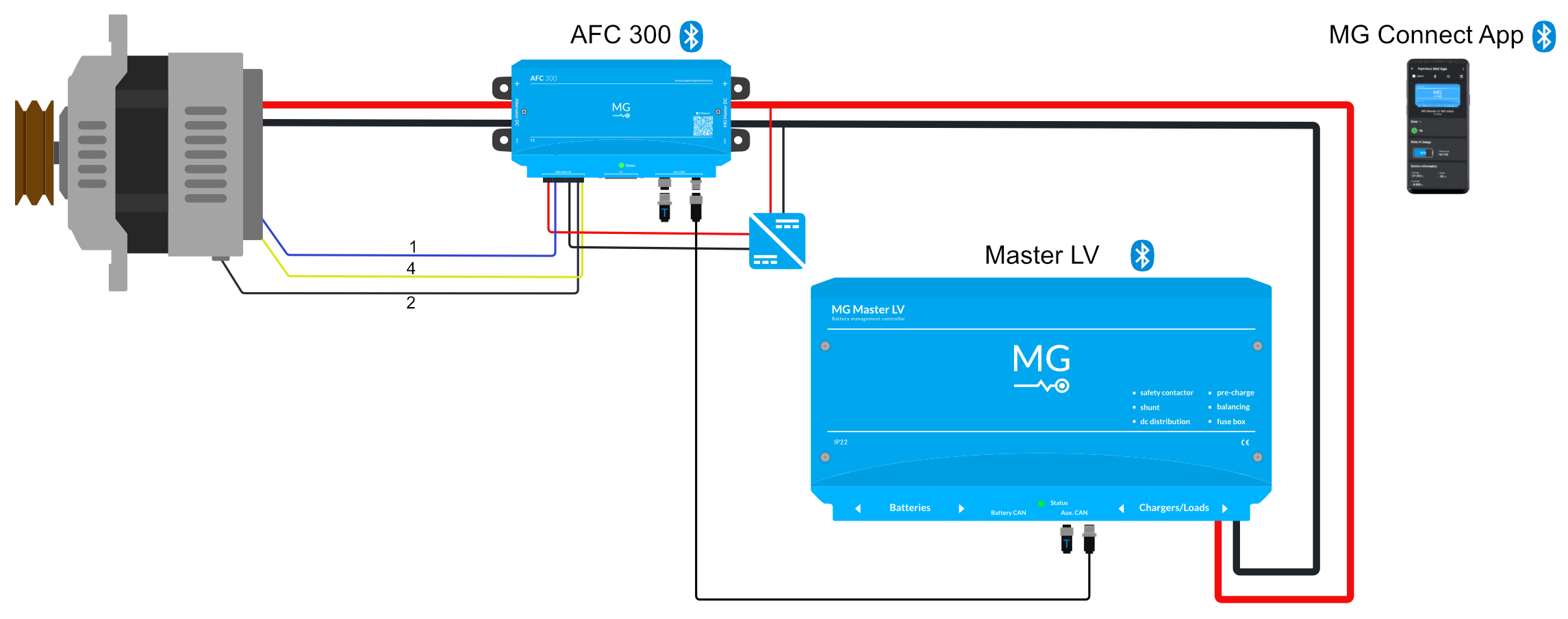
Figure 26:Alternator with W/Tacho (4), field wire (1), temperature sensor (2) and field driven by external PSU.
4.5.4Connect IO connector (optional)
The IO connector on the AFC 300 enables the programmable inputs and outputs as well as the ignition/enable input. See Figure 27 for the IO connector on the AFC 300 and see Table 8 for the pinout specifications.
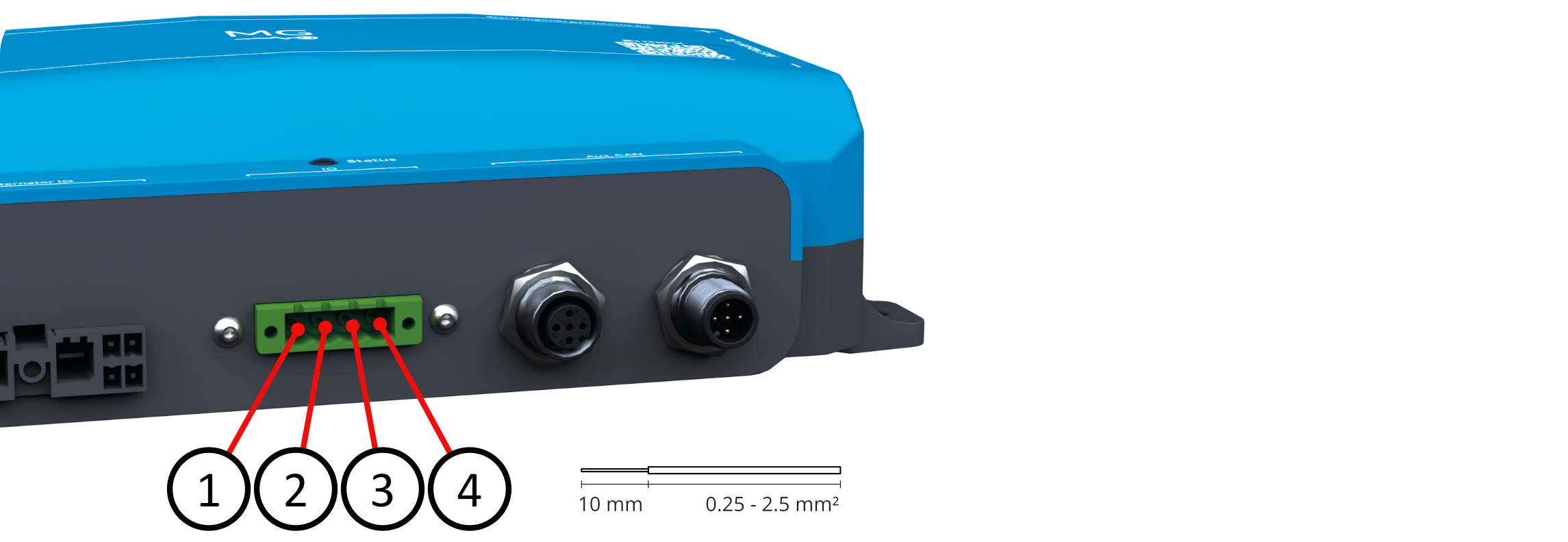
Figure 27:IO connector pins
Table 8:IO connector pinout specifications
| Pin | Name/Purpose | IO | Voltage | Current |
|---|---|---|---|---|
| 1 | Programmable output Return | GND | 0.5 A | |
| 2 | Programmable output | Out | Corresponds to the voltage of “Field power supply +” | 0.5 A |
| 3 | Programmable input (7-58 VDC input for active detect) | In | ≤ 58 VDC | ≤ 1 mA |
| 4 | Ignition/enable (7-58 VDC input for active detect) | In | ≤ 58 VDC | ≤ 1 mA |
Installation steps IO connector
To insert a wire into this connector (see Figure 28):
Raise the top lever (1)
Insert the wire (2)
Lower the lever and press firmly down (3)

Figure 28:Insert wire IO connector
In case this connector should be connected more securely to the AFC 300, tighten the two screws on each side of the connector.
Connecting programmable output: 1 & 2
This output is programmable to one of the following options, each resulting in different behaviors on the output.
List of programmable output options:
Charging: Switch output when AFC 300 is charging above 5 A.
Current: Switch output at a selectable current for programmable threshold times.
AFC temperature: Switch output at a selectable temperature for programmable threshold times.
Alternator temperature: Switch output at a selectable temperature for programmable threshold times.
Failure: Switch output when system is in failure mode.
Off: Disable programmable output feature.
These connections are protected by internal self-resettable fuses. It is powered from S1, the Field power supply +.
Connecting programmable input: 3
This input is programmable to a set of different input options.
List of programmable input behavior:
Enable: enables charging.
Reduced power: reduces alternator charge current limit to a programmable percentage.
Off: disables programmed input feature.
See Table 8 for the threshold at which this input switches.
Connecting ignition/enable wire: 4
This connection can be used to add an external control to start or stop the charging process. This pin is also on the AFC 300 alternator connector (pin S2). For more information about this connection, see Alternator Connector Ignition/enable wire: S2 (optional).
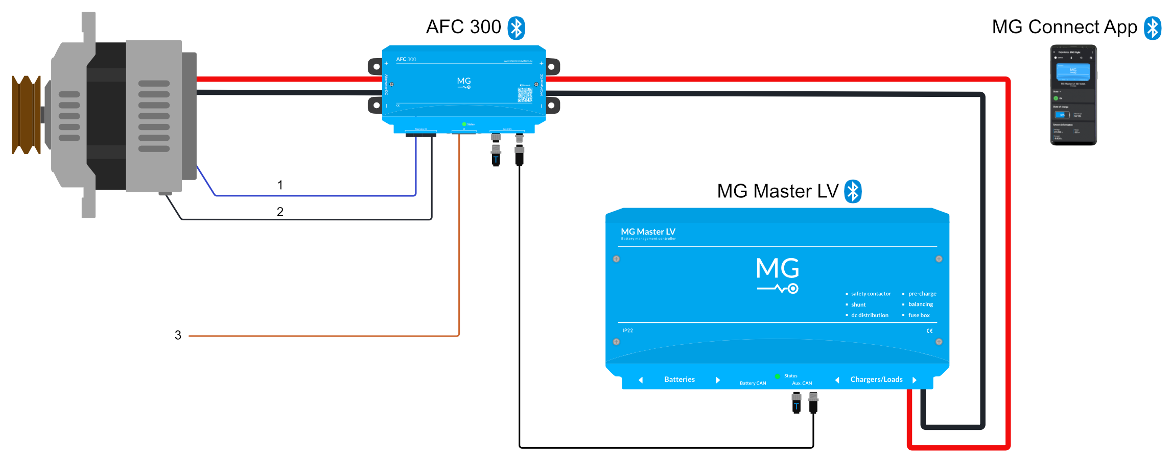
Figure 29:Alternator N/P-type field wire (1), temperature sensor (2) and optional ignition wire (3)
4.6Configuration
To complete the installation, the settings must be configured.
Check if the AFC is mounted and all the cables are connected as instructed.
Verify that the available DC bus voltage range corresponds to the product configuration as described in the product specifications.
Now the system can be powered and configured. Push the start button on the Master BMS (or SmartLink MX), holding it for 3 seconds, to power the battery system.
Configuration is currently only possible with the MG Connect App (Bluetooth).
4.6.1Bluetooth
Follow the next steps:
Step 1/7
Download and install the MG Connect App on your phone or tablet. (Apple or Android)
Step 2/7
Open the MG Connect App and click on the device AFC 300 to connect.
The default password is 000000. If no Bluetooth signal is found, check the Bluetooth switch inside the AFC 300. Refer to Figure 4.
Step 3/7
(optional) You can change the password by clicking the three-dots to open the menu of the AFC 300. Click on Reset pin code to change the password.
Step 4/7
Update the firmware of the AFC 300 by using the MG Connect App (or Victron VRM).
With MG Connect App:
Go to the
Menuby clicking on the three dots.Click on
Device information.Tap on the device you want to update:
AFC 300.Check the Firmware version.
Click the blue
Updatebutton when a new version is available.
With Victron VRM: see this guide for updating the firmware.
Step 5/7
Select the device which should control the AFC 300:
Go to
MenuChoose
SettingsClick on
Selection settingsAt ‘Selection Mode’ choose either
Device instanceorSerial number.Choose the device which should control the AFC 300 (either MG Master LV, MG SmartConnect or MG SmartLink MX).
Step 6/7
Configure the maximum alternator current:
Go to
MenuChoose
SettingsClick on
Charge current limitEnter the maximum current of the alternator. (We recommend entering 50% of the maximum current. See Settings Charge current limit for more information.)
Step 7/7
When required for your application, adjust following settings:
(Optional) Ignition/enable settings
(Optional) Tachometer settings
(Optional) Field voltage limit
Make sure to change the settings that are necessary for your application. Chapter Settings Section 4.6.2 will guide you through the available settings of the AFC 300.
4.6.2Settings
This chapter explains all AFC 300 device settings which can be changed with the MG Connect App. Ensure that you modify the settings necessary for your application.
Open the MG Connect App
Click on the device
AFC 300to connect (default password is000000)Go to
MenuChoose
Settings
Alternator settings
Enable charging
This setting should be set last, right before the test run in the commissioning phase.
The AFC 300 will only power the field when the setting is set to Yes.
This setting is set to No by default and when this setting is kept on No, the field will never be powered.
| Settings | |
|---|---|
| Default | No |
| Options | No - Yes |
Charge current limit
The AFC 300 is pre-configured with a safe-start value of 5 A to prevent immediate alternator overload during the initial commissioning.
Check the documentation of your alternator for the maximum charge current the alternator can safely produce.
We recommend calculating 50% of the rated current and entering this value in the Charge current limit in the device settings.
| Settings | |
|---|---|
| Default | 5 A |
| Range | 0 A to 300 A |
Temperature limit
This setting is protecting the alternator against overheating. The value of this setting determines the maximum temperature that the alternator can safely reach. When the alternator approaches this temperature, the field is reduced as a protective measure. If this temperature is exceeded, an error message is generated and the field is not powered until the alternator has cooled down.
| Settings | |
|---|---|
| Default | 70 °C |
| Range | 50 °C to 90 °C |
Field voltage limit
This setting determines the maximum permissible voltage for the field winding. In some cases, the field needs to be driven with a different voltage than the system voltage. This setting can be used to limit the voltage with which the field winding is driven.
| Settings | |
|---|---|
| Default | 12 V |
| Range | 0 V to 60 V |
| Option | Use system voltage |
Charging startup delay
Change this setting if you wish to set a delay between the standby and charging state.
| Settings | |
|---|---|
| Default | 30 s |
| Range | 0 s to 254 s |
Tachometer installed
This setting determines if a W/Tacho (Stator signal) is supposed to be connected.
In case your application includes a W/Tachometer, this setting should be changed to Yes.
If your application does not have W/Tacho installed, this setting should be set to No.
If no W/Tacho signal is detected while this setting is set to Yes the error Tacho malfunction will be generated.
| Settings | |
|---|---|
| Default | No |
| Options | No - Yes |
Alternator pole count
This setting is only available when the ‘Tachometer installed’ setting is set to Yes.
Find the number of poles in the data sheet of the alternator. The number of poles is always an even number. This number is used to determine the speed of the alternator. The W/Tacho (Stator) is an AC-signal that is proportional to the alternator speed.
| Settings | |
|---|---|
| Default | 16 |
| Range | 2 to 254 |
Drive alternator pulley ratio
This setting is only available when the setting ‘Tachometer installed’ is set to Yes.
This setting concerns the ratio between the diameter of the drive pulley and the diameter of the alternator pulley. The formula for calculating the engine speed is: drive pulley diameter divided by alternator pulley diameter.
| Settings | |
|---|---|
| Default | 3.00 |
| Range | 0.50 to 10.00 |
Current graph
This setting is only available when the setting ‘Tachometer installed’ is set to Yes.
This setting allows you to customize a current graph. The current graph contains up to 10 points. Add the coordinates in the table below the graph. The coordinates on the graph indicate the maximum current at different alternator speeds. The current limit is adjusted linearly between 2 points.
| Settings | |
|---|---|
| Default | 300 A |
| Range | 5 A to 300 A |
Duty cycle graph
This setting is only available when the setting ‘Tachometer installed’ is set to Yes.
This setting allows you to customize a duty cycle graph. The duty cycle graph contains a maximum of 10 points. Add the coordinates in the table below the graph. The coordinates on the graph indicate the maximum field duty cycle. The percentage on the graph is relative to the “Field voltage limit” setting. The maximum field excitation is adjusted linearly between 2 points.
| Settings | |
|---|---|
| Default | 99 % |
| Range | 1 % to 99 % |
Enable tachometer keep-alive
This setting is only available when the setting ‘Tachometer installed’ is set to Yes.
This setting activates the keep-alive function of the tachometer. With this function, the tachometer can still emit a signal without receiving a current from the alternator.
| Settings | |
|---|---|
| Default | No |
| Options | No - Yes |
Tachometer keep-alive margin
This setting is only available when the setting ‘Enable tachometer keep-alive’ is set to Yes.
This setting indicates the margin by which the field duty cycle is reduced relative to the lowest duty cycle at which current is measured.
| Settings | |
|---|---|
| Default | 10 % |
| Range | 5 % to 50 % |
Use external field power
This setting needs to be set to Yes when the field power is supplied by an external power supply.
If the field is supplied by an external power supply while this setting is set to No, an error message for a blown fuse will be generated.
| Settings | |
|---|---|
| Default | No |
| Options | No - Yes |
Ignition/enable installed
This setting determines if an ignition/enable wire is installed.
When this setting is set to No, the ignition/enable wire is ignored.
When this setting is set to Yes, the input needs to be high before the AFC 300 will start charging.
| Settings | |
|---|---|
| Default | Yes |
| Options | No - Yes |
Selection settings
Selection mode
This setting determines whether the AFC 300 should listen to a device instance or a serial number of the specific device that should control the AFC 300 (Master LV, SmartConnect or SmartLink MX).
| Settings | |
|---|---|
| Default | Device instance |
| Options | Device instance or Serial number |
Device instance
Use this setting to select the device that controls the AFC 300 by the device instance. Only one MG device should have this particular device instance. This setting will not change the device instance of the AFC 300 itself.
| Settings | |
|---|---|
| Default | 0 |
| Range | 0 to 250 |
Serial number
Use this setting if you want to select the device that controls the AFC 300 by serial number.
| Settings |
|---|
| List with available devices |
Security
Bluetooth pin code
This setting allows you to change the Bluetooth password, required to connect to the AFC 300.
| Settings | |
|---|---|
| Default | 000000 |
Miscellaneous
Name
If you desire to change the display name of the AFC 300 in the MG Connect App, you can do so in this setting.
Restart
If you want to restart the AFC 300, click on this setting. The MG Connect App will disconnect when the AFC 300 restarts.
4.7Commissioning
After installation and configuration, it is mandatory to inspect and test the system and verify that the configured system is working properly.
Find the commissioning checklist in the Appendix (Section 8.3).
Make sure that the commissioning checklist is fully completed before continuing with the operational phase.
5Operational phase
Once installation and configuration are complete, minimal user effort is required because the MG AFC 300 follows a state machine: a model that changes device behavior when specific conditions are met. This makes the operational phase simple and easy to manage.
5.1Operation
The AFC 300 does not have an on/off button. The device will be powered by switching on the Master BMS (or MG SmartLink MX). The parameters from the Master BMS and the settings in the MG Connect App provide all the information the MG AFC 300 needs to operate optimally.
The operational phase proceeds in stages which are explained in terms of device states. After the AFC 300 is powered, it enters the ‘Starting up’ state. Depending on the information from the Master BMS, the AFC will switch to another state. See Table 9 for a description of each state. Additional details for each state are provided below the table.
5.1.1Device states
Table 9:Device states
| Device state | Meaning |
|---|---|
| Off | System is off and not powered. |
| Starting up | The AFC 300 is powered and will check certain conditions. Receiving data from the Master BMS (or SmartLink MX) can take several seconds. |
| Charging not allowed | The conditions do not allow charging. See Charging not allowed for possible reasons. |
| Standby | The AFC 300 will ramp up the field to its maximum output. And detects if the alternator starts charging. This process will be repeated every 30 seconds. |
| Startup delay | When the AFC 300 detects that the alternator starts charging, it will wait for the startup delay time set in the settings, before going to the ‘Charging’ state. |
| Charging | After the startup delay time, the AFC 300 will control the current from the alternator by adjusting the field. When the AFC 300 no longer detects any charging and the field excitation already reached its maximum, the AFC 300 will go back to the ‘Standby’ state. |
| Failsafe | The AFC 300 enters this state when an error has occurred. In this state, the field is disabled. |
Starting up
During this state, various services and data are collected and initialized. When all data is received and the services are successfully initialized, the AFC 300 will enter either the ‘Standby’ state or the ‘Charging not allowed’ state.
Charging not allowed
The reasons for entering the ‘Charging not allowed’ state:
The device is disabled in the settings.
The ignition/enable signal is low and the ‘Ignition/enable installed’ setting is set to ‘Yes’ in the MG Connect App. (7-58 VDC input for active detect)
The maximum charge current is set to 0 A in the MG Connect App settings.
The alternator temperature exceeds the maximum temperature set in the MG Connect App settings.
No active Master BMS (or SmartLink MX) matches the settings in the MG Connect App.
The active Master BMS does not allow charging.
An error has occurred.
After the above settings have been checked and there are no reasons to not allow charging, the AFC 300 switches to the ‘Standby’ state.
Standby
In the ‘Standby’ state, the AFC 300 will ramp up the field to its maximum output. If, during ramp up, the AFC 300 detects that the alternator is starting to charge, it will immediately switch to ‘Startup delay’ state. If no current is measured when the maximum field excitation is reached, the field is switched off. This process is repeated every 30 seconds.
Startup delay
In the ‘Startup delay’ state, the AFC 300 will wait for the time which is set in the settings in the Connect App. After the time of the startup delay, the AFC 300 will enter the ‘Charging’ state.
Charging
In the ‘Charging’ state, the AFC 300 will try to control the current from the alternator by adjusting the field. The target current and voltage are determined by the AFC 300 settings, the Master BMS and the alternator temperature. In case the AFC 300 no longer detects any charging during this process, and the field excitation already reached its maximum, the AFC 300 will return to the ‘Standby’ state.
Failsafe
In the event of an error, the AFC 300 will switch to a ‘Failsafe’ state. During this state, the field is always disabled. The AFC 300 must be repowered or restarted in the MG Connect App. Also, when no new errors occur for 1 minute after entering failsafe, the AFC 300 will exit this ‘Failsafe’ state.
5.1.2LED status
The status indicator is a two-color LED. This LED indicates the status of the AFC 300. See Table 10 for the LED pattern and its meaning.
Table 10:LED status indicator
| LED light | Blinking pattern | Status |
|---|---|---|
| Off | Continuous | System is off and not powered |
| Green-Off | Rapid flashing | Charging not allowed |
| Green-Off | Long pulse green / flashing off | Standby |
| Green | Continuous | Charging |
| Green-Red | Alternating pulses 5x - repeated | Error |
| Red-Off | Rapid flashing | In bootloader |
5.2Monitoring
Monitor the AFC 300 with the LED status indicator (see Table 10) and with the MG Connect App, via Bluetooth. The MG Connect App displays real-time data, such as the status of the device and its parameters.
5.2.1MG Connect App
The MG Connect App displays the following data:
Status
System information
Speeds
Temperatures
Field values
Charging limits
Status
The MG Connect App displays the status of the AFC 300 device. See Table 11 for the possible status options.
Table 11:AFC 300 status options in MG Connect App
| Status | Description |
|---|---|
| Ok | System is operational, click on v for details. |
| Warning | System needs attention, click on v for details. |
| Failure | System needs attention, click on v for details. |
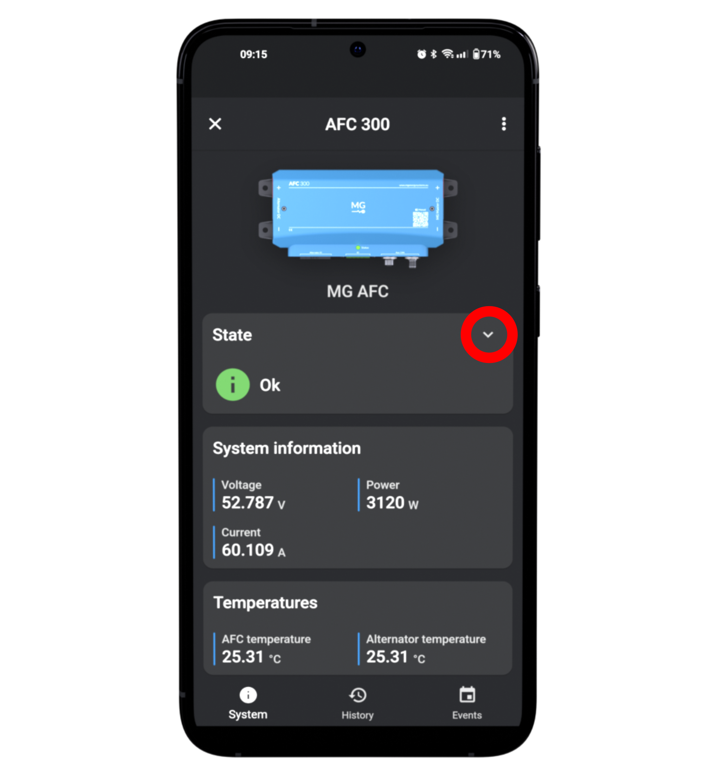
Figure 30:Click on v for more information.
System information
Monitor the parameters (voltage, current, power) of the system. Check the values with the charging limits in the settings to ensure safe operation.
Speeds
This data is only displayed when the ‘Tachometer installed’ setting is set to ‘Yes’. It provides a quick overview of the motor and alternator speed.
Temperatures
Monitor the temperature of the AFC 300 and the alternator. In case the measured value exceeds the set limit, the status will change to warning or failure.
Field values
Monitor the field values: duty cycle, current, voltage.
Charging limits
Quick insight in the charge current limit and the charge voltage limit.
5.3Maintenance
Inspection
We recommend a maintenance schedule of once a year.
Inspect the following:
Check the electrical connections on torque (according to the instructions given in this manual).
Check if all communication connections are mated.
Check for traces of water, oil, moisture, any other fluids or dust.
Check for signs of corrosion.
Clean the device (see Cleaning Paragraph).
Check the status with the MG Connect App.
Cleaning
The device is best cleaned with a dry or slightly damp cloth.
Limit the use of cleaning agents.
If a cleaning agent must be used, it is recommended to use an electrically non-conductive cleaning agent.
It is important to keep the battery areas clean and tidy to minimize the need for cleaning. Avoid moisture and don’t use any liquids, vaporizing agents, oil, grease, etc. near the device.
5.4Troubleshooting
The LED light provides an initial indication of possible problems.
If the LED light is blinking red, this means that the firmware is being initialized. After the firmware is initialized, the LED light turns to green. If this is not the case, check in the MG Connect App if a firmware update is available.
If the LED light flashes green and red alternately, the device is in failsafe mode due to overvoltage and will restart after 1 minute, or an error has occurred. Use the MG Connect App to find out what the problem is or to optionally restart the AFC 300.
The MG Connect App helps identify the error that has occurred.
Open the app, select the AFC 300 device, and the status will indicate ‘Warning’ or ‘Failure’ instead of ‘Ok’.
Check the detailed information under the v button in the MG Connect App and proceed accordingly to resolve the error.
Figure 31:Click on v for more information.
If the error could not be resolved, please send a support request via the MG Connect App.
Click on the three dots to open the menu. Click Request support.
5.5Repair
See Table 12 for the ordering information or contact the manufacturer for a correct replacement.
Table 12:Article order number
| Article | Order number |
|---|---|
| MG AFC 300 | MGAFC480300 |
| IO connector | MG5001095 |
| Alternator connector | MG5001094 |
| Temperature sensor | MG3000438 |
| Fuse FKS ATO 20A | MG5001100 |
| Quick installation guide | MG4000680 |
Never replace a protective device (e.g. fuse) with a component or a different type. See Table 13 for the applicable fuse types.
Table 13:Fuse type
| Fuse Type | Voltage | Current | Brand |
|---|---|---|---|
| ATC | ≤ 32 VDC | ≤ 20 Adc | Bussmann |
| ATO | ≤ 32 VDC | ≤ 20 Adc | Littelfuse |
| FKS ATO | ≤ 80 VDC | ≤ 20 Adc | Littelfuse |
6Disassembly
6.1Decommissioning
Please follow the decommissioning steps:
Turn off the Master BMS (or SmartLink MX) and the alternator.
Verify that no voltages are present on the power connections.
Disconnect the power connections on the MG Master LV or the SmartConnect battery.
Disconnect the power connections on the alternator.
Remove the signal connectors from the Master BMS and the alternator.
Remove all wiring from the AFC.
Remove the AFC from its mounts.
6.2Storage and transportation
The storage and transport instructions must be followed in all circumstances:
Store in the original packaging.
Store in a dry and clean location.
Remove the fuse from the AFC 300 during storage.
Transport the product in its original packaging.
Table 14:Logistics Details AFC 300
| Logistics | Details |
|---|---|
| HS code | 8511800090 |
| Country of origin | Netherlands |
| Product weight | 1.5 kg |
| Classified as dangerous goods | No |
6.3Disposal
The device is treated in accordance with the Waste Electrical and Electronic Equipment (WEEE) Directive 2012/19/EU. Bring the device to an authorized recycling center or a collection point for electronics.
If you are not located within the EU, please consult local laws and regulations for recycling electronic equipment. We recommend bringing the device to a local e-waste collection point that is certified for secure, compliant recycling. Do not dispose of the device with regular household waste.
7Contact details
If you require any further information, please feel free to contact us or our MG dealers.
7.1Head Office
MG Energy Systems B.V.
Foeke Sjoerdswei 3
8914 BH Leeuwarden
The Netherlands
Visit our website: www
7.2MG Dealers
For local contact and support, please contact your dealer. Find your nearest dealer or system integrator in our MG Service Point.
7.3Technical support
In case of a technical question, please consult the options below to find your answer:
Watch the installation videos on our MG YouTube channel.
Consult the MG Knowledge Base.
Check the product’s software version and update to the latest version using the MG Diagnostic Tool or the MG Connect App (Apple or Android).
In case your technical problem was not yet solved, please proceed along the following steps to request assistance:
Contact MG Service Point to request help from your local dealer.
Contact our MG Technical Support team by using one of the options below:
Create a support request using the MG Connect App or MG Diagnostic Tool. (recommended)
Fill in the assistance form at MG Support.
8Appendix
8.1Glossary of terminology
| Term | Description |
|---|---|
| ATC | Allow to charge is a digital output which allows or prohibits charging, based on system conditions or operational criteria. |
| ATD | Allow to discharge is a digital output which allow or prohibits discharging, based on system conditions or operational criteria. |
| Battery bank | A battery bank is one or more battery module(s), combined with a Master BMS. |
| Battery cell | The battery cell is the smallest unit to store energy. Connecting identical cells in series or parallel creates a battery module. |
| Battery module | A battery module is a collection of battery cells. Every MG battery module is equipped with a built-in BMS. |
| Battery string | A battery string is the serial or parallel connection of multiple battery modules. |
| Battery system | A battery system is the combination of one or more battery banks, connected in series or parallel, with auxiliary equipment, creating an operational system. |
| BMS | Battery Management System. A BMS is an intelligent electronic module, integrated into each MG battery module. It monitors all important parameters (voltage, temperature, current) to ensure safe operation of the battery module. The BMS sends data to the Master BMS. |
| Master BMS | Master Battery Management System. The Master BMS is the external control unit of the battery system. It collects data from the BMS in the battery modules and monitors the status and health of all connected batteries. The Master BMS ensures that the system operates within safe parameters and can intervene when necessary to protect all connected battery modules. It also communicates with auxiliary equipment. Every MG battery system requires a Master BMS unit: MG Master LV, MG Master HV, or MG SmartConnect. |
| BOL | Beginning-of-life indicates a value at the beginning of life of the battery module. |
| Busbar | A metallic bar which serves as the central connection point for the distribution of high-current electricity from one source to multiple devices or circuits. |
| CAN bus | Controller Area Network bus is a standard serial data bus, which provides data communication between two or more devices. Use a CAN bus terminator at both ends of the CAN bus. |
| CCU | Charge Controller Unit |
| Contactor | A contactor is an electrically controlled switch, which establishes and interrupts an electric power circuit. |
| C-rate | C-rate is the current (A) used to charge/discharge the battery system, divided by the rated capacity of the battery (Ah). For example for a 100 Ah battery, a 1C rate means a current of 100 Amps to fully charge/discharge the battery in 1 hour. 2C rate means a current of 200 Amps with which the battery would be fully (dis)charged in 30 minutes. |
| DC bus | The DC bus is a power distribution circuit where all user equipment is connected to, for example generators, propulsion systems, or other chargers and loads. |
| DeviceNet | DeviceNet is a network protocol used in the automation industry, to connect control devices for data exchange, standardized in IEC 62026-3. |
| EMS | An Energy management system controls all power sources and consumers in a system. |
| EOL | End-of-life indicates a value at the end of life of the battery module. |
| ESS | Energy Storage System |
| Fail-safe | A condition of adequate level that causes an alarm, causing the battery bank to go into a safe mode when the system happens to fail. |
| HVIL | High Voltage Interlock Loop is a wire loop designed to ensure safe operation of the battery system. When the continuity of the high voltage circuit is interrupted, for example when cables are being pulled during operation, the system shuts down to protect user from electrical hazard. |
| IC | Integrated circuit is an electronic microchip assembled from various electronic components. |
| LFP | Lithium Iron Phosphate (LiFePO4); chemistry of the LFP-battery. |
| MSDS | Material Safety Data Sheet is a document that provides information relating to occupational safety and health for the use of various substances and products. |
| NMEA 2000 | A plug-and-play communication standard on ships that allows electronic devices to seamlessly communicate with each other, developed by National Marine Electronics Association; standardized in the IEC 61162-1. |
| N-type field | In an N-type field the current flows via electrons (negative carriers). If one of the alternator field wires is internally connected to the positive terminal, then the regulator must operate relative to the negative terminal. |
| PCB | Printed Circuit Board is a passive circuitry board without electronic components attached. |
| PCBA | Printed Circuit Board Assembly is an active board consisting of electronic components. |
| PMS | Power management system |
| PPE | Personal Protective Equipment such as gloves, clothing, or eye protection. Choose the right equipment for the hazard and ensure that it fits properly. |
| PPS | Propagation Protection System is a fluid based protection system to prevent cell-to-cell and module-to-module propagation in case of a thermal runaway of one cell. |
| PSU | Power supply unit |
| P-type field | In a P-type field the current flows via holes (positive carriers). If one of the alternator field wires is internally connected to the negative terminal, then the regulator must operate relative to the positive terminal. |
| Quick Installation Guide | A compact and informative manual which guides the system integrator through a quick installation of the product. |
| SoC | State of charge is the remaining capacity in a battery cell or module, expressed in percentage (%) relative to its maximum capacity. 100% indicates fully charged and 0% indicates fully discharged. |
| SoH | State of health reflects the health condition of a battery, about how well it performs compared to its original condition and initial performance. SoH provides insights for i.e. maintenance needs, battery performance or remaining useful life. |
8.2Product data sheet
| Group / Parameter | Value |
|---|---|
| Environmental | Value |
| Humidity (Non-Condensing) | ≤ 95 % |
| Operating Temperature Range | -20 to +50 °C |
| Technical Specifications | Value |
| Supply Voltage Range | 8 - 60 Vdc |
| Supply Current | 21 A |
| Maximum Current | 300 A |
| Maximum Field Control Current | 20 A |
| Power Usage Standby | 1.2 W |
| Communication | NMEA2000 |
| Mechanical | Value |
| Length | 255 mm |
| Width | 132 mm |
| Height | 63 mm |
| Weight | 1.5 kg |
| Enclosure Material | ABS (Reinforced) / PC ABS |
| IP-Protection Class | IP22 |
| Data Connection | CAN-Bus M12 |
| Mounting Feet | 4x max Ø 6.5 mm |
| IO (Input/Output) | Value |
| Programmable Output | Voltage is equal to power supplied on “Field supply +”, 0.5 A, short circuit protection & overcurrent protection |
| Programmable Input | 0-60 V, ≥ 7 V is High/Active |
| Ignition/Enable Input | 0-60 V, ≥ 7 V is High/Active |
| W/Tacho Input | 0 to 58 Vpp |
| Standards | Value |
| EMC: Emission | NEN-EN-IEC 61000-6-3:2021 |
| EMC: Immunity | EN-IEC 61000-6-2:2019 |
| Low Voltage Directive | NEN-EN-IEC 60335-1:2024 |
| RoHs | NEN-EN-IEC 63000:2018 |
| Connectivity | ETSI EN 300 328 V2.2.2:2019 |
8.3Commissioning Checklist
The following checklist needs to be checked during commissioning:
Are the environmental and placement requirements specified in Section 4.3 met?
Is the AFC 300 installed in a location where there is no risk of fluid ingress from above and below? Check also if the AFC 300 is not installed under the seams of hatches.
Is the AFC 300 clean from any dust, metal pieces and loose wires?
Are all power connections in the AFC 300 tightened to 30 Nm (22 lb-ft)?
Are the power cables appropriately fused? (e.g. in the MG Master LV)
Are all CAN bus cables connected?
Are the CAN bus termination resistors installed in the correct way?
Before powering the device, verify that the available DC bus voltage range corresponds to the product configuration as described in the product specifications.
Turn on the system to power the AFC 300.
Check if all settings are correctly set in the MG Connect App.
Is the setting ‘Enable charging’ set to
Yes?Is the ‘Charge current limit’ set to your desired max charge current (recommended is 50% from the alternator’s max charge current)?
Is the right device selected which should control the AFC 300?
Is the AFC 300 detecting the connected field of the alternator? (notified in the status)
Check all other settings when applicable to your application.
Check if the ignition/enable input is functioning properly, when used. (notified in the status)
Perform a charge test run and check the following:
Check if the AFC 300 is able to regulate the alternator current to its set point (charge current limit). The alternator current should not exceed this set point.
During the charge test run, measure the temperature of the power connection terminals on the AFC 300 and on the alternator side, using an appropriate temperature measuring device (e.g. an IR camera). Are all the temperatures of the system and its components within acceptable limits?
Is the W/Tacho input functioning properly? (If used)
Documentation:
Make pictures of the installation.
Send this form together with the pictures and the system commissioning form to support@mgenergysystems
.eu. Please enter in the subject line: Project name - Commissioning.